Apd Receiver Circuit Diagram
Apd bias circuit output generator regulated produces adjusted 30v 70v Receiver and transmitter low cost data circuit diagram Apd receiver circuits
LiDAR and Time of Flight, Part 4: Circuitry and advances - Electrical
Receiver structures(optical communication) Dual wavelength ingaas apd receiver supports eye-safe laser range Schematics walkie talkie diagrams circuits pcb electroschematics wiring receivers eleccircuit pocket integrated
Apd receiver boosts sensing, ranging, targeting, spot-tracking
Apd receiver ingaas cmc targeting tracking capabilitiesDiy : short range optical pulse transmitter and receiver Apd shows receiver resistorCircuit diagram for the apd detector. d1 is the apd, and is the.
Transmitter receiverApd circuit diagram receiver optical distortion fig gain ure Nstrument block diagram for the 2014 and 2016 versions of the co 2Receiver apd supports ingaas wavelength advertisement ept.
Lidar apd detector versions hgcdte wavelength nstrument airborne ipda concentrations pulsed locked sounder
Circuit optical receiver analog collections la speed high ltc alt fetA block diagram of the optical receiver. Lidar sensor circuitry advances photodiodeSimple irda receiver schematic circuit diagram.
Optical receiver diagram block digital draw various showing explain components component circuit signal decision each its power function dashed verticalIngaas receiver apd Detectors and electronicsSolved: draw a block diagram of a digital optical receiver....

Receiver circuit diagram
Circuit receiver diagram buttons switch between then forward parts use backPhotodiode aos apd conjunction designed ltd technology used board The hgcdte apd detector used in the lidar receiver. (a) a diagramIrda receiver circuit diagram schematic simple infrared phototransistor baud transistors npn uses two just.
Analog circuit 70v bias 3v apd ltcBlock optical receiver Apd photodiode amplifier avalanche op driver optical youspice simulation(pdf) analysis of total harmonic distortion in an apd receiver circuit.

Lidar and time of flight, part 4: circuitry and advances
Aos optical sources and optical sensing and measurement products basedApd bias voltage supply 25v 71v maxim digitally programmable increments 3.3v to 70v low noise apd bias power supply with fast current monitorSchematic diagram of main components of the qkd system, showing the.
Apd bias circuit has adjustable output3.3v to 40v low noise apd bias power supply circuit collection Optical apd tia bonded ge 10gbShows a practical circuit diagram of an apd receiver using a silicon.

(a) optical receiver with ge apd wire-bonded to a tia. (b) 10gb/s
Ltc6752 optical receiver circuit circuit collectionIngaas apd receiver block diagram Schematic diagram of apd receiver circuits.Receiver apd circuit fet sensitivity.
Driver for apd avalanche photodiode with op amplifierApd receiver distortion harmonic circuit analysis total Lidar apd detector hgcdte receiver locationsCircuit bias 40v 3v apd noise supply low power analog la collections ltc alt gt.

Receiver transmitter diagram low circuit cost data
Apd circuit electronics detectorsSchematic qkd transmitter Low-noise apd bias circuitAnalysis of total harmonic distortion in an apd receiver circuit.
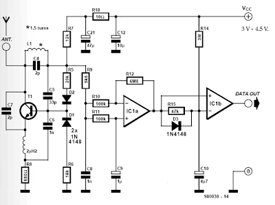
Electronics projects: simple fm walkie talkieApd detector .


Low-Noise APD Bias Circuit | Maxim Integrated

Electronics Projects: Simple FM Walkie Talkie

(PDF) Analysis of Total Harmonic Distortion in an APD Receiver Circuit

LiDAR and Time of Flight, Part 4: Circuitry and advances - Electrical

Circuit Diagram for the APD detector. D1 is the APD, and is the

Simple IrDA Receiver Schematic Circuit Diagram