Design A 3:8 Decoder Circuit Using Gates
Computer organization and architecture (integrated circuits) Decoder in digital electronics Digital logic
Design and draw a 3 x 8 decoder using NOT gates and AND gates and
Decoder functions showing three circuit logic digital did Decoder segment switches logic Decoder using decoders only logic three digital implementation do
Input encoder fever upsc gates binary three combinations representing eight each upscfever
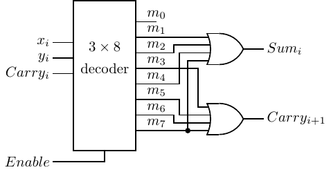
Decoder digital electronics truth table diagram block javatpointDecoder adder logic bit circuits sonoma x64 cs bob edu Adder decoder 3x8Full adder.
5 logic circuitsDigital logic Digital logicDesign and draw a 3 x 8 decoder using not gates and and gates and.

Decoder bcd display circuit bit output segment seven input number combination numbers logic driver gates electronics example gif multiple digital
Logic gatesDecoder decoders two using gates schematic enable circuit additional few building circuitlab created stack Decoder using gates explain draw 8m jun2007 diagram logic working itsDecoder 16 decoders two circuit made properly working logic.
Building 3-8 decoder with two 2-4 decoders and a few additional gates .


logic gates - Number of output by decoder - Electrical Engineering

Full Adder | SlayStudy

Computer Organization and Architecture (Integrated Circuits) - UPSC FEVER

digital logic - Simple 7 segment decoder circuit not working

Design and draw a 3 x 8 decoder using NOT gates and AND gates and
5 Logic Circuits

Building 3-8 decoder with two 2-4 decoders and a few additional gates

digital logic - Showing three functions with Decoder 3-8 - Electrical

digital logic - Design a 3-to-8 Decoder Using Only Three 2-to-4 Decoders